Complete Guide for Nokia 5110 LCD with Arduino
Complete Guide for Nokia 5110 LCD with Arduino
This post aims to be a complete guide for Nokia 5110 LCD with Arduino. I’ll explain what it does, show its specs and share an Arduino project example that you can take and apply to your own projects.
DESCRIPTION
The Nokia 5110 LCD is very popular among the Arduino tinkerers. These modules are used on wide variety of applications that require some sort of interface or display data to the user.
hese modules are very cheap and you can use them with any microcontroller (MCU).
Specifications Nokia 5110 LCD
- 84*48 dot matrix LCD (shows 4 lines of characters)
- Price: $2/$3
- Voltage: 3.3V
- Module size: 45.2mm x 43.1mm
- Model: Nokia 5510
- Controller: PCD8544
Arduino with Nokia 5110 LCD
You need the following components to make this example:
- 1x Arduino
- 1x Nokia 5110 LCD
- 1x Potenciometer
- 4x 10K Ohm Resistors
- 1x 1k Ohm Resistor
- 1x 330 Ohm Resistor
- Breadboard
Library download
Here’s the library you need for this project:
- Download the PCD8544 library
- Open your Arduino IDE
- Go to Sketch > Include Library > Add .ZIP Library
PINOUT
1) RST – Reset
2) CE – Chip Enable
3) D/C – Data/Command Selection
4) DIN – Serial Input
5) CLK – Clock Input
6) VCC – 3.3V
7) LIGHT – Backlight Control
8) GND – Ground
2) CE – Chip Enable
3) D/C – Data/Command Selection
4) DIN – Serial Input
5) CLK – Clock Input
6) VCC – 3.3V
7) LIGHT – Backlight Control
8) GND – Ground
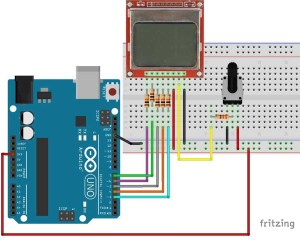
SCHEMATICS
The Nokia 5110 LCD operates at 3.3V. So you can’t connect the Arduino Uno digital pins directly.
I’ll be adding some resistors in series with the data signals to protect the 3.3V lines.
Using Logic Level Converters to switch from 5V to 3.3V is the best option to interact with this LCD.
UPLOADING SKETCH
After installing the PCD8544 library in your Arduino IDE, you can find the sketch below in File > Examples > PCD8544 > HelloWorld.
/*
 * PCD8544 - Interface with Philips PCD8544 (or compatible) LCDs.
 *
 * Copyright (c) 2010 Carlos Rodrigues <cefrodrigues@gmail.com>
 *
 * To use this sketch, connect the eight pins from your LCD like this:
 *
 * Pin 1 -> +3.3V (rightmost, when facing the display head-on)
 * Pin 2 -> Arduino digital pin 3
 * Pin 3 -> Arduino digital pin 4
 * Pin 4 -> Arduino digital pin 5
 * Pin 5 -> Arduino digital pin 7
 * Pin 6 -> Ground
 * Pin 7 -> 10uF capacitor -> Ground
 * Pin 8 -> Arduino digital pin 6
 *
 * Since these LCDs are +3.3V devices, you have to add extra components to
 * connect it to the digital pins of the Arduino (not necessary if you are
 * using a 3.3V variant of the Arduino, such as Sparkfun's Arduino Pro).
 */

#include <PCD8544.h>

// A custom glyph (a smiley)...
static const byte glyph[] = { B00010000, B00110100, B00110000, B00110100, B00010000 };

static PCD8544 lcd;

void setup() {
  // PCD8544-compatible displays may have a different resolution...
  lcd.begin(84, 48);

  // Add the smiley to position "0" of the ASCII table...
  lcd.createChar(0, glyph);
}


void loop() {
  // Just to show the program is alive...
  static int counter = 0;

  // Write a piece of text on the first line...
  lcd.setCursor(0, 0);
  lcd.print("Hello, World!");

  // Write the counter on the second line...
  lcd.setCursor(0, 1);
  lcd.print(counter, DEC);
  lcd.write(' ');
  lcd.write(0);  // write the smiley

  // Use a potentiometer to set the LCD contrast...
  // short level = map(analogRead(A0), 0, 1023, 0, 127);
  // lcd.setContrast(level);

  delay(200);
  counter++;
}
Demonstration
After you upload the sketch your LCD should print the words: “Hello, World!”.
I hope you found this guide useful.
Share this post with a friend that also likes electronics!
You can contact me by leaving a comment. If you like this post probably you might like my next ones, so please support me by my Facebook Page.
Thanks for reading,
LetsMakeRobots


Comments
Post a Comment